FRPico!
Oct 7, 2024
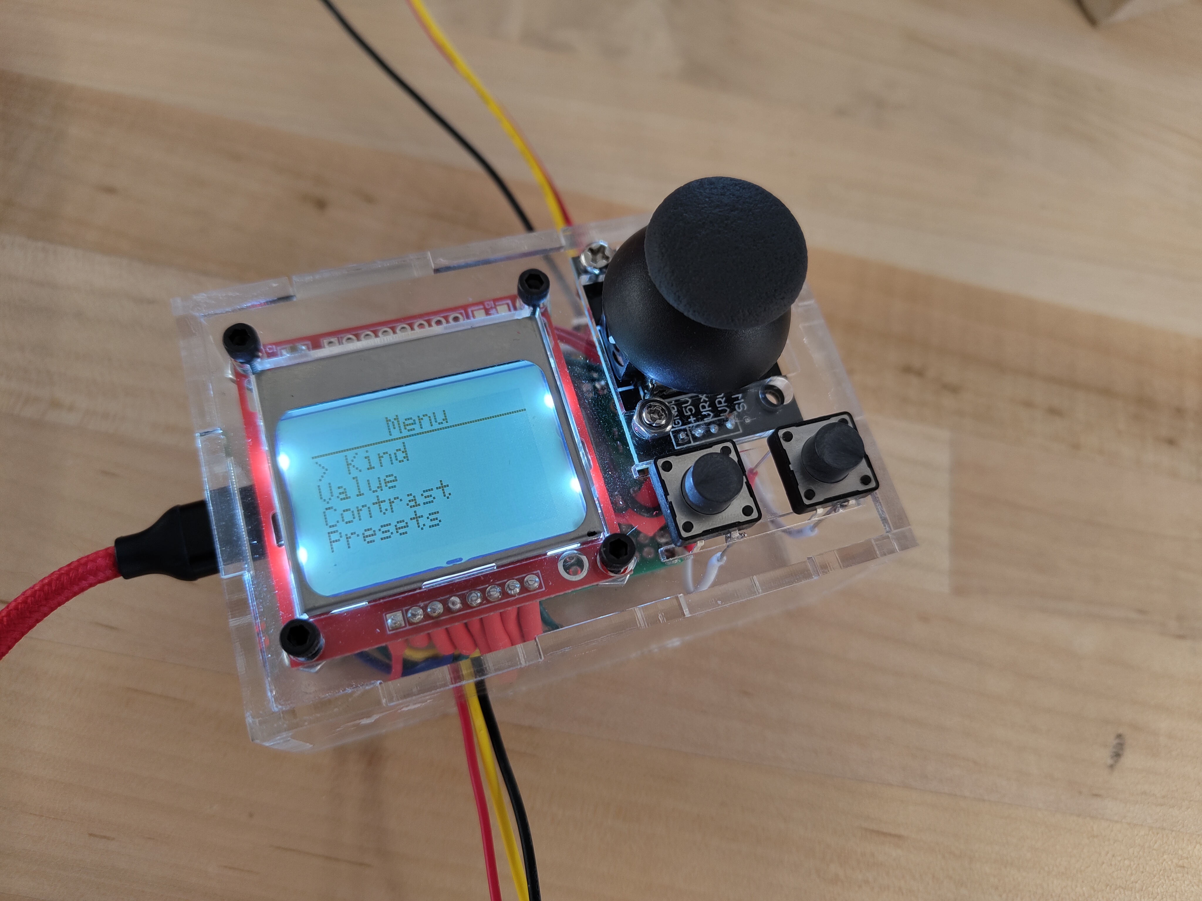
FRPico is a physical model of a probability box (an "FRP") from Professor Genovese's Probability for Computer Scientists course (36-218). I built FRPico with Anna Lee for our 18-095 final project. We implemented this project in CircuitPython. You can view the source code here.
You can read more about what an FRP is here. Essentially, it is a device with a probability distribution etched onto it. Pressing a button on the device "observes" the FRP, and produces a random value according to that distribution. FRPs can also be initialized with a conditional distribution, meaning that the distribution changes based on an input value. This means that FRPs can also be chained together! Each FRP has an input port to receive data from the previous FRP in the chain, and an output port to transmit its observed value to the next FRP in the chain.
We set out to make a real-life version of this box based on a Raspberry Pi Pico.
Parts List
- One Raspberry Pi Pico
- A Nokia 5110 LCD
- A joystick
- Two pushbuttons
- JST connectors
- A soldering breadboard
- Acrylic to cut a case out of
Note: though you might buy your LCD from another supplier, the Adafruit CircuitPython Library for this display will likely be easier to work with.
IO Diagram
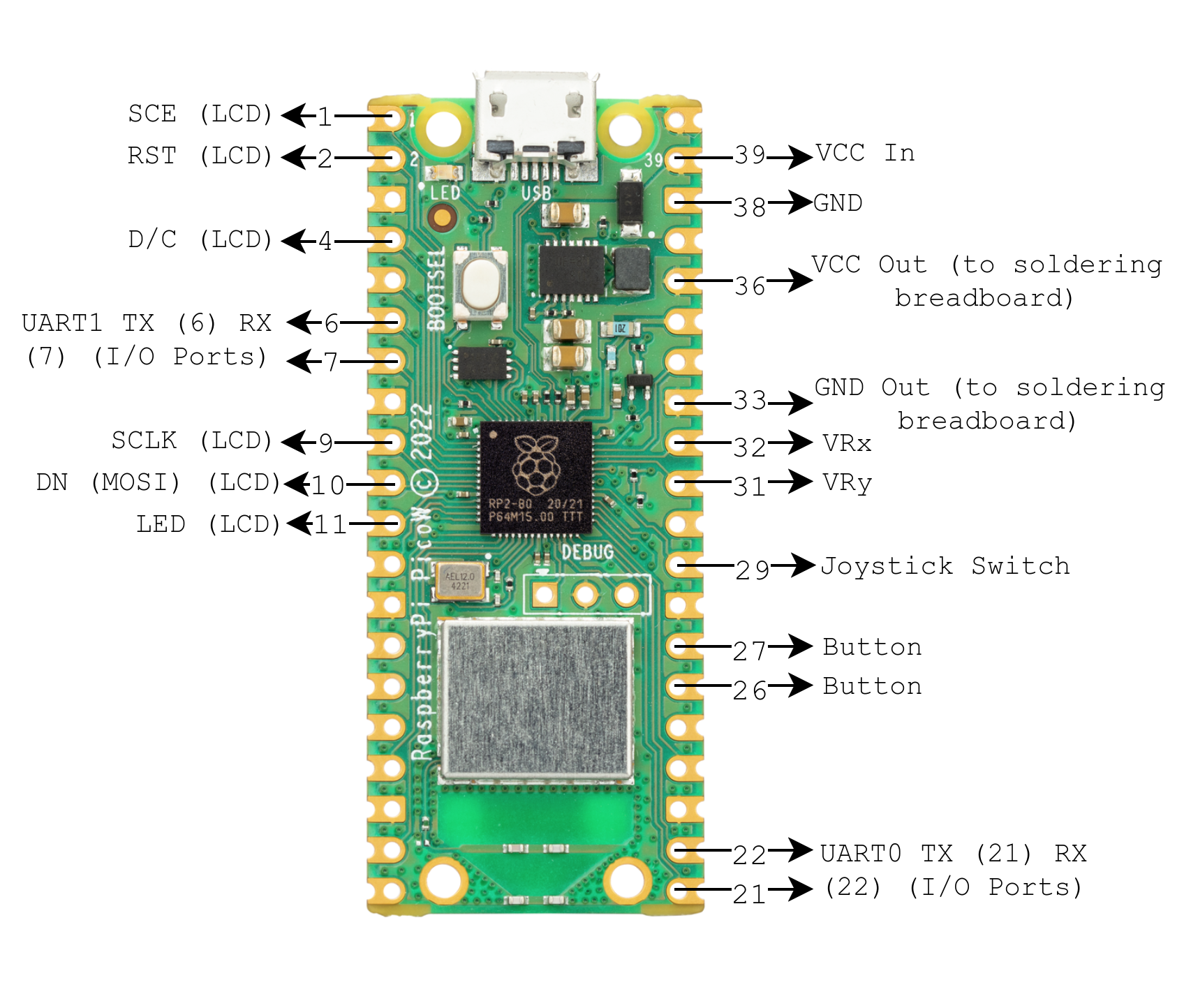
The above image shows an IO diagram for FRPico. Note that if you want to chain multiple Pi Picos together, you should use different UART channels for the input and output ports (e.g. output on UART1, receive on UART0).
Modes
The functionality of FRPico is implemented through cmu-112-graphics-inspired modes. The current mode informs what each button press or joystick movement should do. For example, if you are on the menu screen, moving the joystick moves you in the menu, and the joystick button selects menu items. In the "contrast" mode, the joystick lets you dial in the contrast of the display.
Pico-to-Pico Communication
One of the most interesting parts of this project was implementing communication between FRPicos over UART. The UART code we used was adapted from this guide by Adafruit. We show a truncated version of our program's main loop here:
    UPDATE_INTERVAL = 3.0
    last_time_sent = 0

    # Wait for the beginning of a message.
    message_started = False

    while True:
        now = time.monotonic()

        if rcvdValue != None and isinstance(frp, ConditionalFRP):
            frp.giveObserved(rcvdValue)

        # UART Attempt - TX
        if now - last_time_sent >= UPDATE_INTERVAL and frp.isObserved():
            observedValue = frp.getObserved()
            if isinstance(observedValue, float):
                uartTX.write(bytes(f"<f,{observedValue}>", "ascii"))
            else:
                uartTX.write(bytes(f"<i,{observedValue}>", "ascii"))
            last_time_sent = now

        # UART - RX
        byte_read = uartRX.read(1)  # Read one byte over UART lines
        if not byte_read:
            # Nothing read.
            continue
        if byte_read == b"<":
            # Start of message. Start accumulating bytes, but don't record the "<".
            message = []
            message_started = True
            continue

        if message_started:
            if byte_read == b">":
                # End of message. Don't record the ">".
                # Now we have a complete message. Convert it to a string, and split it up.
                message_parts = "".join(message).split(",")
                message_type = message_parts[0]
                message_started = False

                if message[0] == 'i':
                    rcvdValue = int("".join(message[2:]))
                else:
                    rcvdValue = float("".join(message[2:]))
            else:
                # Accumulate message byte.
                message.append(chr(byte_read[0]))
Here, uartTX is the channel we have dedicated to transmitting observed values, and uartRX is the channel we have reserved for receiving them.
Transmitting
First, we check whether we have an observed value to transmit in the first place. If we do, we transmit it at regular intervals along our "TX" channel. We transmit the data as an ASCII string in a consistent format: <f,{observedValue}> if we are transmitting a float, and <i,{observedValue}> if we are transmitting an integer. The angle brackets (< and >) allow the receiver to detect the beginning and end of a message.
Receiving
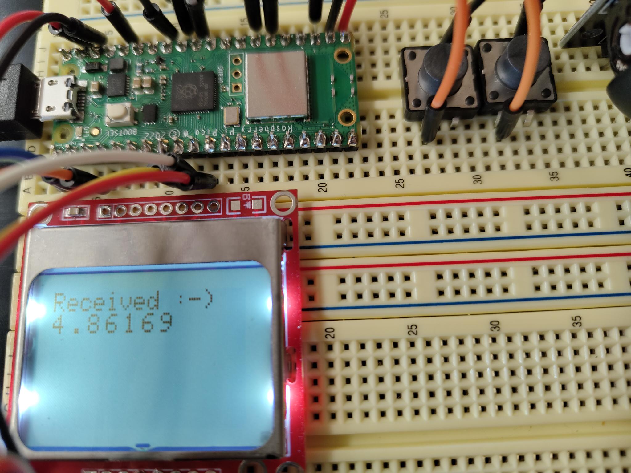
On each iteration of the loop, the receiver tries to read a byte from the "RX" (receiving) channel. If we see <, then we can start building up the message in message. If we see > then we know the message has ended. We stick together what we have so far in message and convert it to an integer or a float as appropriate.
Putting it all Together
We built the original FRPico demo on a pair of solderless breadboards.
Towards the end of the project, we wanted to transition to real boxes. So, we set about moving our design onto soldering breadboards, and switching out the breadboard jumper wires we were using for communication for real cables with JST connectors. Here's a photo of an FRPico being assembled! We used heatshrink on the ends of wires to prevent them from interfering with each other.
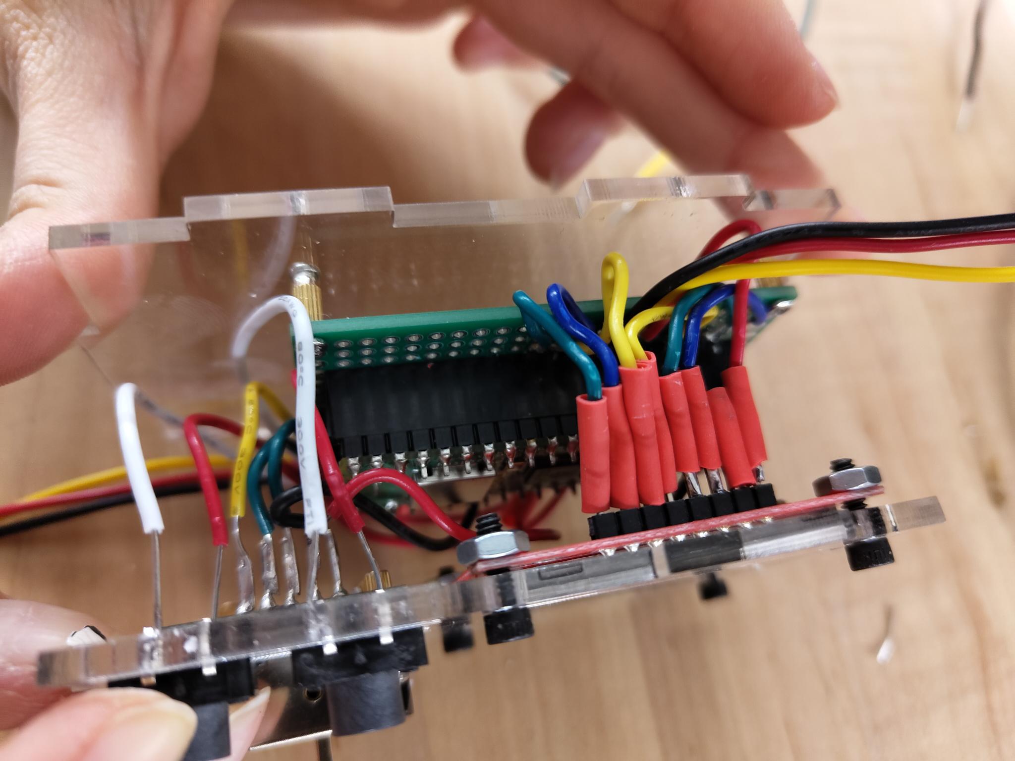
All of the soldering was easily the most difficult part of this project. We needed to solder a connection for each of the wires shown in the IO diagram three times over (so we could make a chain of three FRPicos). We were very fortunate to receive help and advice from Professor Kesden, who would come visit the lab sometimes.
Laser-Cutting an Enclosure
The enclosure of FRPico is made out of clear acrylic, which nicely shows off the internals. We used this tool to make our initial case design, and then used Inkscape to add screw-holes and cutouts for our components:
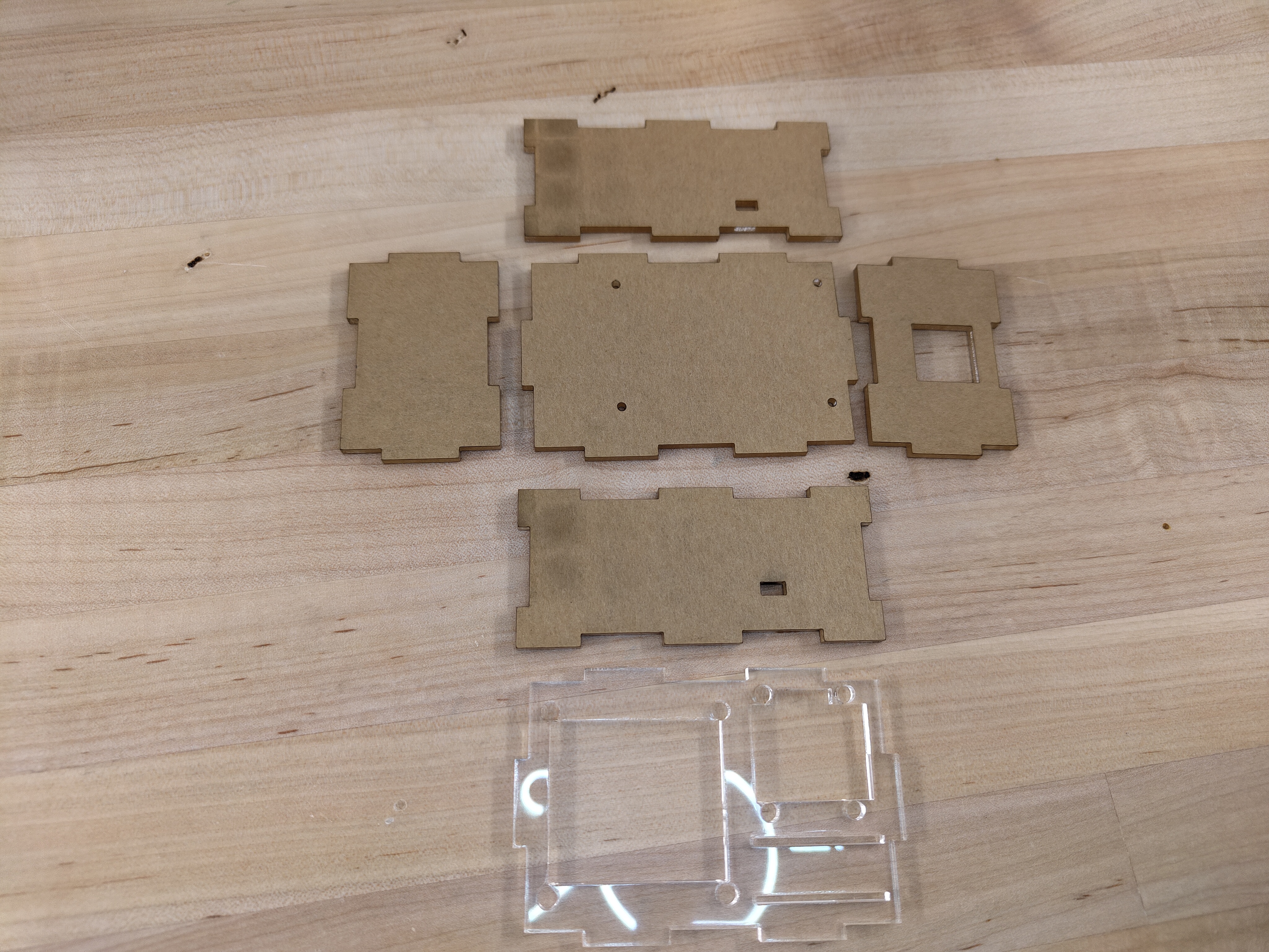
The case is held together with glue applied to all of the joints. Luckily, TechSpark had all of the screws we needed to secure the joystick and the LCD to the case.
Acknowledgements
- Anna Lee
- Professor Genovese
- Moises Gavarrette (our TA)
- Professor Zajdel
- Professor Kesden (for helping us fix our soldering!)